|
|
| to bluebox website... |
bluebox
tech doc
General The building "Blauer Bock" is very symmetric and has got 8 floors. Each of the upper 7 floors has got 98 windows with almost the same size. Those floors are used for the light installation "bluebox". Therefore, a 150W construction light has been placed behind each of 686 windows. All of these lights are wired to a single computer to turn the entire building into a giant display with 98x7 pixels (i.e. every window is a pixel). The graphic [bluebox.svg] gives an overview about the wiring in the building. ![[bluebox]](bluebox.jpg) Rooms Most rooms (22 on every floor) have got 4 windows, but there are also 2 rooms with 5 windows on every floor. Thus, the entiere wiring was based on 4 lights per room. The rooms with 5 lights are treated as two virtual rooms (with 3 lights missing in the second room). To be able to talk about certain rooms, every (virtual) room got a letter. When viewed from the outside, the room "A" is to the left and the room "Z" is to the right. The uppermost floor is called "7" and the lowermost floor of the display is called "1". The graphic [bluebox.svg] shows a schematic drawing of the building including the numbering of the rooms and the wiring of the lights. To reduce cost and cable length, a single electronic circuit controls 4 lights - i.e. a (virtual) room. This electronic circuit is called "BlueBrightnessControl4" and is shown as a blue circuit in [bluebox.svg]. Power Distribution Every "BlueBrightnessControl4" needs mains power for the lights connected to it. 4 circuit boards (not counting the two circuit baords in every floor with only a single light) are connected using normal power extension cords (shown as thin red lines in [bluebox.svg] to the floor power distribution - shown as red circle in the graphic. 6 fuses and a FI switch are located there. Every floor power distribtuion panel is connected (bigger red lines) to the main power distribution panel in the 1st floor (red square). There are additional fuses for every floor. The main power cable goes downstairs into the basement to the power meter where the electricity arrives in the building. Data Distribution The data wires are drawn as green lines in [bluebox.svg]. Every "BlueBrightnessControl4" is connected to the main data distribution module of the floor located in the L room. For this connection, simple twisted pair cables are uses. On those twisted pair cables, a serial protocol similar to the protocol used by the serial port of normal PCs is used. The main data distribution modules are called "BlueDataDistributor" and supply data received from 10MBit ethernet to the 26 serial lines. The ethernet wires go to the 4th floor where a simple 8-port ethernet switch is used to connect the 7 ethernet lines to a single 100MBit ethernet cable that goes to the computer. BlueBrightnessControl4 (BBC4) ![[BBC4]](BBC4.jpg)
The BBC4 can be separated into 3 main parts: power input, logic part and output. The single parts are described in the following sections. The graphic [BBC4.svg] provides an overview over the internals of the BBC4. The power supply for the logic part is the 4th part, but this is not described here, because it is very standard and thus not interesting. Power Input The task of the power iput part is to provide a half sine wave voltage that can be used to generate the PWM. It is important to filter the current drawn by the PWM so that the mains power soes not see the fast rising and decaying currents. Of course, the power input starts with a fuse to protect the BBC4 against catching fire in case of a short circuit or a similar problem. After this, the current passes a (not current compensated) coil, the rectifier. At the end, there is a big capacitor in parallel. The rectifier is a full bridge rectifer composed of fast high power diodes and transforms the mains voltage into the needed half sine wave voltage, i.e. a pulsating voltage with always the same direction. The coil and capacitor are used to filter the current drawn from the mains power. The coil is dimensioned to keep the current almost constant during a PWM period (32 microseconds) while having almost none effect to the current in the much longer half sine wave periods (10 milliseconds). Similarly, the capacitor is dimensioned to keep the voltage almost constant during the PWM periods but to not store any voltage during the longer half sine wave periods. This means that there is still a half sine wave voltage at the capacitor and not an almost constant DC voltage with some ripple on it like in simple power DC supplies with a bridge rectifier and a huge capacitor. Thus, the current at the input is always a sine in phase with the mains voltage and carries very little PWM noise. Logic Part The logic part is responsible to receive the brightness levels from the serial line and generate the 4 PWM signals. It also checks if data is coming in and shows the state using a LED. A button can be used to override the incoming data and turn on single lights for a few seconds. This is useful for checking if all lights are still working. The serial data is recevied via an optocoupler to insulate the data wires from the mains voltage. The mircocontroller (CPU) shares the ground with the rectified mains power to simplify the FET drivers. It simply generates the 4 PWM signals with 32kHz based on the last brightness levels recieved. In case of timeout on the serial input, the lights stay off if they were in the off state or an internal animation is started if the lights were on before the timeout. In any case, the button overides the serial input or the internal animation for a few seconds. The status LED blinks one two or threee times in a row before being off for a longer time. Blinking once means serial data arrives and is being processed. If the internal animation is running or the lights stay off the LED blinks twice. Blinking three times happens whenever the button was used to turn on a single light or all of the lights. Output The output circuit is the same for each of the 4 lights and consists only of a high power filed effect transistor (FET) and a driver circuit to switch the FET on and off fast enough. The fast switching is important, because most losses occur during the switching and heat up the FET. This effect can be minimized by turning on and off the FET as fast as possible. BlueDataDistributor (BDD) ![[BBC4]](BDD.jpg)
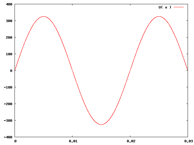
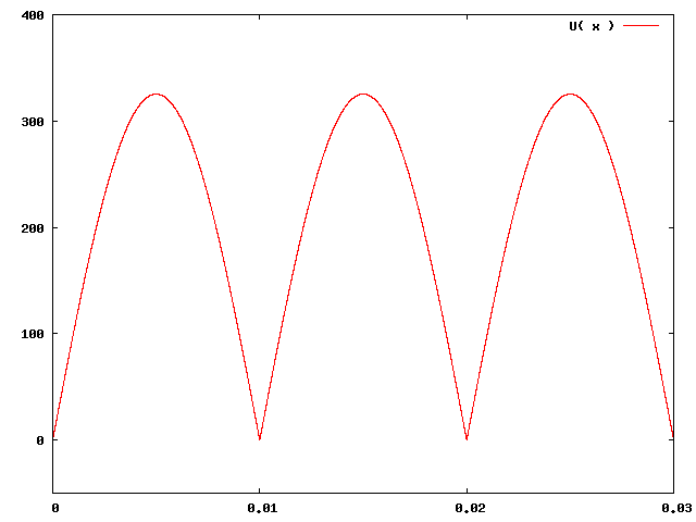
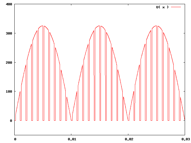
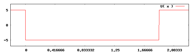
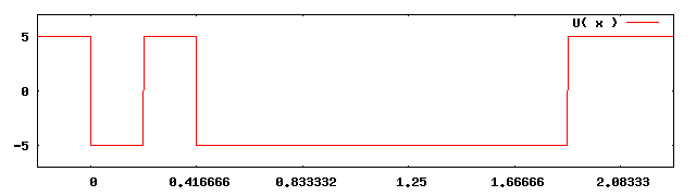
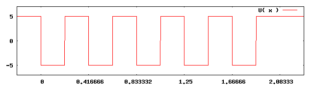
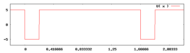
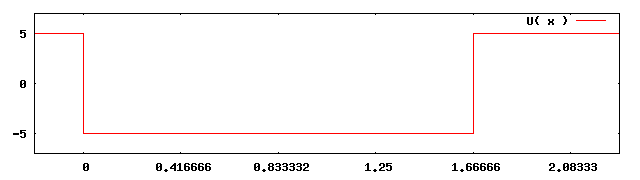
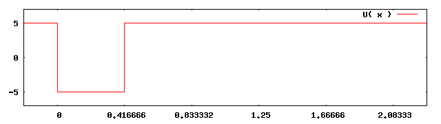
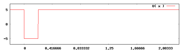
The data distribution module, called BlueDataDistributor, receives the data to display from ethernet and splits it up to 32 serial lines. It does also show if data is arriving via a status LED as can be seen in [BDD.svg]. Ethernet Interface The 10baseT ethernet interface is realized using a similar chip as on older ISA network cards known from normal PCs. This chip simply handles filtering the received ethernet messages by destination MAC address. This destination address is build by the microcontroller (CPU) on power up by appending the byte configured via the config switches to a fixed part and is then written to the filter register of the ethernet chip. Everything else on top of basic ethernet, like ARP, IP and UDP is done by the microcontroller in software. It assembles an IP address out of a fixed part and the byte from the config switches and then starts responding to ARP queries and received UDP datagrams. Every UDP datagram received on the correct port is then split up into blocks of 32 bytes (discarding the remaining 0 to 31 bytes). Those data block are then passed on to towards the outputs. Status LED The status LED simply gives information about the state of the data reception. Normally, when data is arriving regularly, it blinks once and then stays off for a longer time. If no data to output is recived for some time, this timeout condition is detected and visualized by blinking the status LED twice before turning it off for a longer period. Thus, it can be easily seen if data is arriving. Serial Outputs Every data block with 32 bytes recevied on the UDP port is outout on the 32 outputs. Each byte in this block is output at a different serial line simultaneously with 4800bps in NRZ coding. The start bit before the data bits and the stop bit afterwards are automatically generated. The 32 outputs of the microcontroller are then amplified, once non-inverting and once inverting. Thus, every output drives two lines antisymmetrically with 0V and +5V. Pulse Width Modulation (PWM) of rectified AC power It's not very easy to control the brightness of 150W construction lights smoothly and using relatively cheap electronics. The main problem is that normal light dimmer circuits behave very impolite to the mains power. E.g. for half brightness, they turn on the light only for the first part of every half sine wave on the line. This results in a current not closely related to the voltage which is very bad for the transformers in the mains power network. (There are also light dimmer circuits that turn on the power in the second part of every half sine wave, but this is only better, not really good.) However, it is not allowed to control more than a dozen of 150W construction lights this way. The main idea was to use Pulse Width Modulation instead. This means that the current through the lamp is turned on and off very quickly. If the light shall be bright, the current is turned on most of the time and if it shall be dark, it is turned off most of the time. To be able to do PWM with AC current, the PWM frequency must be a lot faster than the AC power frequency. This is needed to ensure that the voltage does not change significantly during a single PWM cycle (i.e. turning on once and turning off once). For realizing this idea, the voltage must be switched on and off at arbitrary times very fast. Thus, no triac can be used, because this type of electronic switch can only be turned off when the voltage (the current, but this is the same for lights) becomes zero. The second idea was to use the rectified mains voltage for the PWM because it doen't matter for the lights in which direction the current flows. Then, the PWM switching can easily be done using high voltage field effect transistors (FETs). The image [ac.png] shows the mains voltage that arrives at the BlueBrightnessControl4s. This voltage is then rectified (see image [rect.png]) which results in a half sine wave voltage pulsating with 100Hz. On top of this pulsating voltage, the PWM is applied with 32kHz, i.e. the current is turned on and off 320 per half sine wave. This cannot be shown in the graphics because this would be too fine for the graphics. Therefore, the images [pwm.off.png], [pwm.low.png], [pwm.medium.png], [pwm.high.png] and [pwm.on.png] show PWM signals generated with a PWM frequency of 1kHz at five different brightness levels (off, low, medium, high, on). Serial Data Protocol The serial data is transmitted over twisted pair wires using the standard protocol also used on the serial ports of normal PCs, i.e. NRZ coding of the single bits. The basic data entities are 8 bits wide and are transmitted using 4800bps with a single start bit and a single stop bit. Physical Layer To be more resistant against noises on the wires than the standard serial port of normal PCs, a simplified version of a current loop is used instead of the +12V/-12V used with normal serial ports. The sender side outputs 0V on the A wire and +5V on the B wire for a logic 1 and +5V on the A wire and 0V on the B wire for a logic 0. At the recevier side, there is a resistor and the LED of an optocoupler (with a normal diode in reverse parallel for the other direction) to complete the circuit. This results in a current almost constant in value, but differing in direction for a logic 1 and a logic 0. Noises now inducing into the wire will induce almost the same voltage into both wires, thus changing almost nothing of the current flowing. Bits are encoded using non return zero (NRZ) coding, i.e. by simply putting a logic 1 or logic 0 onto the wires for an entire bit time. The bit time is 208.333us resulting in 4800bps. Link Layer For illustration, the images [serial.x00.png], [serial.x01.png], [serial.x55.png], [serial.x7F.png], [serial.x80.png], [serial.xFE.png] and [serial.xFF.png] show the voltage between the two wires (A negative and B positive terminal of the voltage meter) when transmitting some values (0x00, 0x01, 0x55, 0x7F, 0x80, 0xFE and 0xFF). There is always a logic 0 as start bit, followed by the least significant bit. The other bits are sent up to the most significant one before the transmission is completed by a logic 1 as stop bit. Application Layer The application protocol used is very simple. The first byte of each message can be recognized by the set most significant bit. This bit is cleared for all further bytes of a message. The first byte gives the type of the message and implicitly also the number of additional bytes. There is a command to turn off the lights, which ony consits of a single byte. The normal command to set the brightness levels of the 4 lights connected to a BBC4 consists of 4 additional bytes specifying the brightness levels from 0 to 127. Trailing bytes with the most significant bit cleared are ignored. Incomplete messages (i.e. a byte with the most significant bit set is received too early) are also ignored. Control ![[control]](control.jpg)
The main control of bluebox consists mainly out of a normal PC with an ISDN interface card and 2 ethernet inferface cards. Additionally, there's some telecommunication equipment to connect the computer to the ISDN lines and the internet. The phone and DSL line arrives in the basement and is extended to the main control computer using twisted pair cable. The graphic [control.svg] shows that this line then arrives at the DSL splitter. The phone part is passed on to the NTBA where it is converted into the ISDN S0 bus that is connected to the ISDN interface card of the computer. The DSL part is connected to a generic DSL router that connects the computer (and a small LAN used for working) to the internet. This is done via the first ethernet interface. The second ethernet interface is reserved for sending data to the BDDs. From there, a twisted pair (cat. 5) ethernet cable extends to the ethernet switch in the 4th floor, to which the 7 BDDs in the different floors are connected. Software ![[software]](software.jpg)
The software on the control computer consists mainly of 4 parts (see [software.svg] for reference). The ISDN lines are converted to a network protocol called Extended Blinken ISDN Protocol (EBIP) to connect them to the main software block, the Blinkenlights Chaos Control Center (blccc) which has been extended with some modules for bluebox. The pixel data generated by the blccc is then sent using the Micrcontroller Unit Frame protocol (MCUF) to bl_proxy, which is used here to distribute the stream to users on the internet and to blue_dist. blue_dist finally receives the MCUF stream and splits up the pixel data before sending it to the BDDs in the appropriate format. blinkenisdn blinkenisdn is a Perl script written by the Blinkenlights people for Blinkenlights Arcade to control some ISDN lines. Other programs can connect to it as clients using the Extenden Blinken ISDN Prototcol (EBIP) to be informed of incoming calls. Whenever a programm accepts a call via EBIP, blinkenisdn will manage the ISDN stuff and start playing some background sound file on the ISDN line. Additionally, keys pressed on the calling phone are detected and passed to the client program via EBIP. blccc blccc (Blinkenlights Chaos Control Center) is the main control application of bluebox. It was also written by the Blinkenlights people for Blinkenlights Arcade. Its main task is to play the movies from the playlist. However it is also posible to extend this playlist with BModules that can be written by anybody who is able to write glib C code. A BModule is a shared library that can be "played" as a movie from the playlist. Thie means the library is loaded and then called to generate pixel data to display. E.g. the BText module (originally written by the Blinkenlights people, but extended for the bluebox project) will look for a short text message to diaplay and render it onto the display if a message is found. Of course, this module may not be used too frequently, because text is the most boring thing to display. Pixel data is output using the Microcontroller Unit Frame protocol (MCUF) via UDP to a single receiver, bl_proxy in the bluebox setup. The blccc connects to blinkenisdn via EBIP and will then accept calls from the ISDN lines. When being called, a default BModule is started, BPongMulti in the bluebox setup. Using codes ("*code#") the active module can be switched. It is also possible to switch to a so called loveletter, i.e. a film not in the playlist that can be accessed using a code. While the ISDN connection is active, pressed keys are received via EBIP and are reported to the active module. Thus, it is possible to play games on the bluebox display. Three games have been written for the bluebox setup. BPongMulti is a pong game with multiple balls. The additional balls had to be introduced because the bluebox display is very wide and playing with a single balls becomes boring very fast. In the bluebox context, this game is simply called Pong. BPacman is a pacman implementation with some game fields for different display sizes (of course also one tailored to the bluebox display). As usually, the Pacman has to be eat all the dots while avoiding the ghosts. Due to the low resolution there are only two ghosts and no powerups for Pacman to collect that make the ghots edible. In BPacman, the ghosts become vulnerable if Pacman has collected all dots. Then the ghots can be eaten to finally win the game. BSitris4 is a Tetris clone for wide displays. There, the stones come from the sides and "fall" towards the middle of the display. To decrease the logical size of the display, two pixels horizontally next to each other form a single logical pixel. Additonally, the field is mirrored in the middle of the display. Thus a single logical pixel is displayed 4 times on the physical display. In the bluebox context, this game is called Symmetris. bl_proxy bl_proxy is a tool for receiving, selecting and re-distributing pixel data while being able to convert between the different protocols and display formats. Based on a set of flexible rules, bl_proxy will detect and filter incoming streams. It then assignes different priorities and timeouts to those streams according to the rules before passing the streams to one or more outputs. Every output will select the stream with the highest priority that has not yet timed out and send the frames coming from that stream to its clients. Those clients can be configured statically or can join dynamically. While receiving and sending stream, bl_proxy can convert between the protocols Blinkenlights Protocol (BLP), Extended Blinkenlights Protocol (EBLP) and Microcontroller Unit Frame protocol (MCUF). It is also able to resize pixel data and/or convert the number of channels and the number of colors used. In the bluebox context, bl_proxy is only used for MCUF streams with 98x7 pixels and one channel. It receives only the stream from blccc and forwards it to blue_dist and zero or more dynamic clients in the internet. blue_dist To split up and convert the MCUF stream into the correct format for the BDDs, blue_dist is used. It is able to split up the pixel data in every received frame into multiple parts according to its configuration and convert the parts into commands for the BBC4s. Those commands are then packed together for all BBC4s connected to a single BDD. The data blocks for the BDDs are sent using UDP over ethernet. Whenever blue_dist detects a timeout of the incoming stream it sends turn-off commands to the BBC4s via the BDDs. This allows to turn off the display during the day by simply stopping the stream sent from bl_proxy to blue_dist. |
![[bluebox tec]](bluebox-tec.jpg)